Difference between revisions of "PortLinking"
(→Schema) |
|||
| Line 87: | Line 87: | ||
The user should be able to specify the recursion depth. A default could be stored in the Config table, but the user should be able to modify the depth setting by changing a field in the trace pop-up window. If an object or port has additional links which are not displayed due to the depth limit, it should be marked somehow (perhaps colored green). Clicking on it would reload the page with that object/port becoming the "subject" which is traced. | The user should be able to specify the recursion depth. A default could be stored in the Config table, but the user should be able to modify the depth setting by changing a field in the trace pop-up window. If an object or port has additional links which are not displayed due to the depth limit, it should be marked somehow (perhaps colored green). Clicking on it would reload the page with that object/port becoming the "subject" which is traced. | ||
| − | The recursive trace function needs to be modified to handle all link types. Loops could become very common if both types were treated the same. | + | The recursive trace function needs to be modified to handle all link types. Loops could become very common if both types were treated the same (a port may have both physical and logical links, both ending at the same port). |
= Circuits = | = Circuits = | ||
Revision as of 21:26, 12 December 2013
Core Goals
- Determine which port(s) a specified port is physically connected to.
- Determine which port(s) a specified port is logically connected to.
- Graph the link(s) a port traverses before reaching its final destination.
- Graph the traversal of all links associated to an object.
- Provide the ability to trace ports of "contained" objects.
DB Changes
Schema
Current columns in the Link table:
- porta
- portb
- cable (cable ID)
New columns:
- type (physical, logical or unspecified)
- cable type (reference a dictionary entry)
- cable color (varchar [loose] or reference a dictionary entry [strict]?)
- length
- notes
Current columns of the Port table:
- id
- object_id
- name
- iif_id
- type
- l2address (only applies to data ports)
- reservation_comment
- label
New columns which only apply to power ports in most cases (PoE ports are the exception):
- voltage
- maximum wattage
- average wattage
New Port Types
It would be helpful to provide an image of each type. Also, the types listed are used in the USA, international support should be added.
Power (receptacle)
- IEC C14
- IEC C20
- NEMA 5-15R
- NEMA 5-20R
- NEMA L5-20R
- NEMA L6-20R
- NEMA L6-30R
Power (plug)
- IEC C13
- IEC C19
- NEMA 5-15P
- NEMA L5-20P
- NEMA L5-30P
- NEMA L6-20P
- NEMA L6-30P
- NEMA L15-20P (208V Delta)
- NEMA L15-30P (208V Delta)
- NEMA L21-20P (208V WYE)
- NEMA L21-30P (208V WYE)
- NEMA CS8365C (208V Delta)
Cable Types
- Thicknet Coaxial (10Mb)
- Cat-3
- Cat-4
- Cat-5
- Cat-5e
- Cat-6
- Cat-7
- Multi-mode Fiber
- Single-mode Fiber
- Twin-axial (10Gb)
Tracing Feature
When tracing a port or an object, the user should be able to choose which links are included in the graph:
- Port Type
- Data
- Power
- Both
- Link Type
- Physical
- Logical
- Both
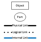
The appearance of links on the graph should vary depending on the type. If the color of a link is specified, it should be used on the graph.
The user should be able to specify the recursion depth. A default could be stored in the Config table, but the user should be able to modify the depth setting by changing a field in the trace pop-up window. If an object or port has additional links which are not displayed due to the depth limit, it should be marked somehow (perhaps colored green). Clicking on it would reload the page with that object/port becoming the "subject" which is traced.
The recursive trace function needs to be modified to handle all link types. Loops could become very common if both types were treated the same (a port may have both physical and logical links, both ending at the same port).
Circuits
The tracing feature described above depends on intermediate ports being linked more than once. Due to the one-to-many design, a traversed link may have multiple endpoints.
An alternative is to use manually-defined circuits, which would have only one start and one endpoint. In the case of links with multiple endpoints, multiple circuits would need to be defined.
Circuit table definition:
- id
- name (some may want to name circuits by hand)
- description
- start_port_id (calculated, not directly user-modifiable)
- end_port_id (calculated, not directly user-modifiable)
CircuitStep table definition:
- id
- circuit_id
- step
- start_port_id
- end_port_id
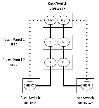
Example: Through Patch Panels
A server is connected to a switch, passing through two patch panels. Assume that 8P8C ports use '1-88' as their type.
SELECT * FROM Port;
+----+-----------+------+--------+------+-----------+---------------------+-------+
| id | object_id | name | iif_id | type | l2address | reservation_comment | label |
+----+-----------+------+--------+------+-----------+---------------------+-------+
|  1 |         1 | eth0 |      1 |   24 | NULL      | NULL                |       |
|  2 |         2 |    8 |      1 |   88 | NULL      | NULL                |       |
|  3 |         3 |    8 |      1 |   88 | NULL      | NULL                |       |
|  4 |         4 |  gi0 |      1 |   24 | NULL      | NULL                |       |
+----+-----------+------+--------+------+-----------+---------------------+-------+

SELECT * FROM Circuit WHERE id = 1;
+----+------+-------------+---------------+-------------+
| id | name | description | start_port_id | end_port_id |
+----+------+-------------+---------------+-------------+
|  1 | C219 | host1 to R1 |             1 |           4 |
+----+------+-------------+---------------+-------------+

SELECT * FROM CircuitStep WHERE circuit_id = 1;
+----+------------+------+---------------+-------------+
| id | circuit_id | step | start_port_id | end_port_id |
+----+------------+------+---------------+-------------+
|  1 |          1 |    1 |             1 |           2 |
|  2 |          1 |    2 |             2 |           3 |
|  3 |          1 |    3 |             3 |           4 |
+----+------------+------+---------------+-------------+
Notes
- Using the circuit model, the existing Link table would only be used to document physical links. All logical links would need to be replaced with circuits.
- A significant amount of preemptive logic would need to be written to make circuit management feasible. Consider these cases:
- When racking an object, ports must be linked and circuits must be created. This imposes more labor than auto-discovering paths using the original recursive traceroute logic.
- Original: Link eth0 to PP1 port 1 (record the physical connection).
- Circuit-based: Link eth0 to port 1 (record the physical connection). Create a new circuit, noting connections to PP1 port 1, PP2 port 1 and R1 port gi0.
- What happens when an intermediate port or object is deleted?
- When racking an object, ports must be linked and circuits must be created. This imposes more labor than auto-discovering paths using the original recursive traceroute logic.
- In the provided table definition, Start and End port IDs are included in the Circuit table to reduce the effort required to determine the values. This is a form of de-normalization. Also, the values may become inaccurate if CircuitStep data is manually altered. Circuits use one-to-one links, so a recursive PHP or MySQL function could be used instead. A MySQL function may not be feasible because recursive calls are disabled by default. A PHP function may be too resource intensive, notably when viewing an object with several hundred ports. Further testing is warranted.
Misc Notes
- In the case of breaker panels, one-to-many links are common. A 120v circuit uses one breaker, a 208v circuit uses two, and a three-phase circuit uses three.
- The CDP/LLDP/802.1Q features, as they exist today, expect a direct link between neighbor ports to exist. It may be either physical or logical (or both?).
- For simple cases, such as connecting a server directly to a switch, defining two links could be considered too much work. Users shouldn’t be forced to define both physical and logical links between ports.
Use Cases
Patch Panels
- From a logical perspective, Rack Switch-Fa0/1 is directly connected to Core Switch1-Gi0/7.
- Tracing a port should only display items which directly participate in the path.
- Tracing an object should trace each port and merge the results.
- Tracing can be done using recursion of physical links, since intermediate ports are linked twice, while end-point ports are only linked once.
WAN Links
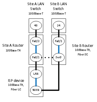
- From a logical perspective, Site A Router-Fa0/1 is directly connected to Site B Router Ser0.
- The ISP device is past the point of demarcation, totally outside the control of the customer. The customer may or may not wish to document ISP connections at the same level of detail as connections under his control.
- Adding a port compatibility rule to allow 100Base-Tx connections to Fiber SC ports could be considered a sub-optimal approach.
- Tracing cannot be done using recursion of physical links, since intermediate ports are only linked once.
- Establishing additional “internal” links between the "LAN" and "WAN" ports of devices would allow tracing to succeed.
Physical Multi-point Links
Multi-port cable
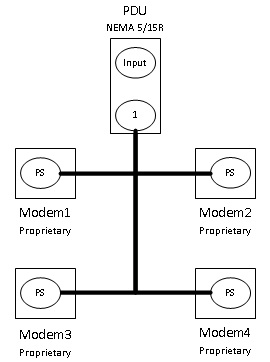
- Each modem uses an AC adapter with a proprietary connection.
- The same design can be applied to "Y" power cables which connect directly from the input source to device power supplies.
- An octo-cable is used to power up to eight modems from a single outlet.
- A similar methodology applies to QSFP+ connections – a one-to-four "breakout" cable.
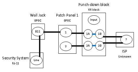
Splicing
- The 66 block is considered "horizontal wiring".
- The bundle of cables between the 66 block and the ISP is considered "vertical cabling".
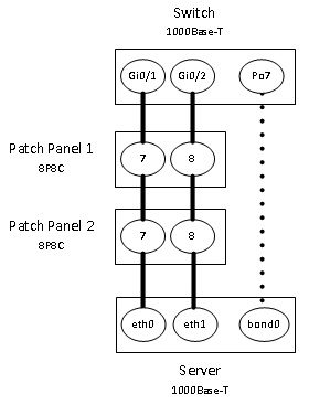
Bonding
- Server is a Linux host. eth0 and eth1 are slaves of the bond0 virtual interface, which uses mode 4 (802.3ad).
- Switch is a Cisco switch with an LACP PortChannel interface containing Gi0/1 and Gi0/2 as members.
- The example equally applies to switch-to-switch interconnections.
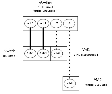
Virtual Links
- A virtual switch may contain both physical (uplink) and virtual (connect to VMs) ports. It may be used on a single host or distributed across multiple hosts.
